Controlling a single 5V DC motor, and a 12V DC thru an Arduino.Both are same connections -except that for a 5V, the Vss Motor Supply ( pin 8) will be fed 5V from the wall adapterfor a 12V, the Vss will be fed 12Vwall adapter, and the GND will be common across all.Connect Pins 8 and 9 of the Arduino to Pins 3 and 7 of the L293DArduino L293DPin 8 Pin 7Pin 9 Pin 2GND -> GND // or else it wont work Pin 4 -> GND Pin 5 -> GND Pin 1 -> +5V Pin 16-> +5V ( or tie them up) Pin 3 -> Output to Motor Pin 6 -> Output to Motor Pin 2, and 7 ( as described above, goes to Arduino Pins 8 and 9) Pin 8 -> motor supply +5V ( Pin 1, 16 and Pin 8 - can all be tied to +5V)For a 5V motor Pins 1..8 on left and Pin 16 are connected to connect a single DC motor in case of a 5V.) Pin 8 -> +5V ( all of them as 5V )For a 12V motor Check 1 and 16 are internal - so 5V. Pins 8 is +12V For a 5V DC motor.
 For a 12V DC motor.
 void setup(){ pinMode(8,OUTPUT) ; //Logic pins are also set as output pinMode(9,OUTPUT) ; Serial.begin (9600);}void loop(){ forward_motor (); delay(3000) ; stop_motor (); delay(3000); backward_motor (); delay(3000); stop_motor (); delay(5000); } void forward_motor () { Serial.println ("forward"); digitalWrite(8,HIGH) ; digitalWrite(9,LOW) ; } void stop_motor () { // Stop Serial.println ("Stop " ); digitalWrite(8,LOW) ; digitalWrite(9,LOW) ; } void backward_motor () { Serial.println("backward"); digitalWrite(8,LOW) ; digitalWrite(9,HIGH) ; }
Controlling a single 5V DC motor thru an Arduino.Connect Pins 8 and 9 of the Arduino to Pins 3 and 7 of the L293DArduino L293DPin 8 Pin 7Pin 9 Pin 2GND -> GND // or else it wont work Pin 4 -> GND Pin 5 -> GND Pin 1 -> +5V Pin 16-> +5V ( or tie them up) Pin 3 -> Output to Motor Pin 6 -> Output to Motor Pin 2, and 7 ( as described above, goes to Arduino Pins 8 and 9) Pin 8 -> motor supply +5V ( Pin 1, 16 and Pin 8 - can all be tied to +5V) ( check that Pins 1..8 on left and Pin 16 are connected to connect a single DC motor )  void setup(){ pinMode(8,OUTPUT) ; //Logic pins are also set as output pinMode(9,OUTPUT) ; Serial.begin (9600);}void loop(){ forward_motor (); delay(3000) ; stop_motor (); delay(3000); backward_motor (); delay(3000); stop_motor (); delay(5000); } void forward_motor () { Serial.println ("forward"); digitalWrite(8,HIGH) ; digitalWrite(9,LOW) ; } void stop_motor () { // Stop Serial.println ("Stop " ); digitalWrite(8,LOW) ; digitalWrite(9,LOW) ; } void backward_motor () { Serial.println("backward"); digitalWrite(8,LOW) ; digitalWrite(9,HIGH) ; }
A small demo of how I was able to communicate from my laptop using a python code sending commands to the Arduino Uno using a Cloud broker called cloudmqtt.com and turn on and off a LED.https://github.com/kiranshashiny/python-cloudmqtt-exampleThis uses the Paho MQTT library on the laptop to publish commands like ON and OFF.The code to run on the laptop as well as the Arduino sketch is in the repo.
This blog is about my Stepper motor that I used to control using an Arduino Uno.A Stepper motor works in steps and there are times when you need to move the motor in steps -like in a wall clock. This is where the motor comes handy.( the other types of motors are Servo, and DC motor - more of it in other blogs.) Here I will control the Stepper motor and tell how to make it work with the Arduino Uno.Cost :Stepper Motor :125 rupeesULN 2003 : 7 rupees.Arduino Uno : 400 rupees.Time to put it all together - one afternoon -including debugging and figuring out the wiring.Skill level : Beginner to Medium.Stepper Motor :The stepper motor that I used is 28BYJ-48 and can be programmed to spin in steps to suit our industrial needs. It needs a 5V external power supply and I used a wall adapter. DO NOT use the 5V from Arduino !!!The challenge was that after wiring the circuit and I executed the File -> Examples -> Stepper - > One Step Revolution, the motor would only move in 1 direction ( counter clockwise ) and would not do clockwise.So, I had to change the wiring of Pin 9 to 10, and Pin 10 to 9 on the Arduino - to make it work.Found the link here. https://forum.arduino.cc/index.php?topic=143276.0In other words - don't pin 8,9,10 and 11 to Input 1, 2, 3 and 4, but instead pin to Input 1, 3 , 2 and 4 on the ULN 2003.( the source in the File -> Examples had to be modified to make this work )The next challenge is - this Motor driver ULN 2003 cannot move the motor direction on a DC motor. ( You cannot control a DC motor in reverse )So this motor driver can only be used for a Stepper Motor and NOT a DC motor.DO NOT CONNECT the Output pins of the Arduino to the Stepper Motor as you will fry your Arduino- Use the IC in between to make this work.Have a 5V power supply ( wall adapter ) handy to work with the motor.The circuit diagram of a ULN 2003 motor driver is as shown :The inputs on the left are from the Arduino Pins and Outputs will go to the Stepper Motor. You are still left with 3 more Pins after all this.
 The circuit is as shown: ( the only correction is Pin 9 and 10 has to be interchanged )


Hardware Required:
- Micro controller ( Arduino Uno )
- Arduino Ethernet shield
- HC 05 Bluetooth adapter ( not required for beginners)
- LEDs – Red, Green, Yellow - 10 each ( or something on those lines )
- ESP 8266 for wifi communication
- 1 Breadboard a foot long.
- Connector wires
Male to Male - 1 set,
Female to Female connector wires - 1 set
General purpose wire - about 5 meters ( for everyone )
Sensors:
- Temperature and Humidity sensor DHT 11
- PIR sensor for motion sensor. ( for detecting if someone came in etc )
- Color Recognition Sensor ( if we are getting into detection of colors, like tablets , or paper )
- Soil Moisture sensor ( if we are into agriculture or conditions where we want to maintain humidity high / low )
- Pressure sensor ( if we want to detect presence of someone on the door step )
- Heart Rate sensor ( medical related stuff )
- Rain Drop Sensor ( for Agriculture, labs, mechanical objects, if we want to Close doors On/Off based on certain humid conditions)
- Light detecting Resistors, LDRs - 10 ( general purpose, if we want to do some solar stuff )
- Ultrasonic Distance Measuring Sensor
- Water flow sensor
Other things nice to have :
- Piezo buzzer ( to make sound music )
- 1 Servo motor SG90 Tower Pro ( general purpose )
- 12V DC motors - 100 RPM - geared
- 5V DC motors
- LCD display
General purpose utilities :
- 1 Multimeter
- 1 Piezo buzzer
- L293D, 555 timers
- Magnifying glass
- Small screw driver set.
- Wire stripper
- Nose plier
- Soldering wire, gun and other accessories.
- 10k Potentiometer
- a box of resistors ( usually costs 40 rupees for it - has 220, 270, 330 ohms and so on )
- RGB LEDs - a few


On the source server,ssh-keygen -t rsa copy the id_rsa.pubto remote server's .ssh/authorized_keysPossible reasons why the scp will not work are :On the remote server checkAuthorized_keys needs perms of 600 (chmod 600 authorized_keys)
The .ssh directory should be 700
Your home directory should be at most 744
Code in Python:Here I am using the Raspberry Pi Model B, connected to my Mac Laptop.This was an experiment to try out using the PWM option available on the Raspberry.The LEDs are connected to physical Pins 11 The white LED at one end is connected to Pin 11, ( i.e the GPIO17 ) , hence I'm using GPIO.BOARD in the python definition.pi@raspberrypi~ $cat servo.py import RPi.GPIO as GPIO # always needed with RPi.GPIO from time import sleep # pull in the sleep function from time module GPIO.setmode(GPIO.BOARD) # choose BCM or BOARD numbering schemes. I use BCM GPIO.setup(11, GPIO.OUT)# set GPIO 11 as output for white led white = GPIO.PWM(11, 100) # create object white for PWM on port 11 at 100 Hertz white.start(0) # start white led on 0 percent duty cycle (off) # now the fun starts, we'll vary the duty cycle to # dim/brighten the leds, so one is bright while the other is dim pause_time = 0.02 # you can change this to slow down/speed up try: while True: for i in range(0,101): # 101 because it stops when it finishes 100 white.ChangeDutyCycle(i) sleep(pause_time) for i in range(100,-1,-1): # from 100 to zero in steps of -1 white.ChangeDutyCycle(i) sleep(pause_time) except KeyboardInterrupt: white.stop() # stop the white PWM output GPIO.cleanup() # clean up GPIO on CTRL+C exit
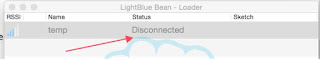
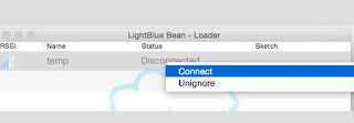
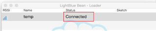
In this blog I will write about how to configure and setup the Bean Punchthrough micro controller and blink a LED for the first time.The Punch through is a simple micro controller with an ATmega chip embedded on to a chipset and a built in proto board.It runs on a 3V battery and connects through Bluetooth and is perfect for prototyping or for small projects. Programming wireless makes it convenient to program thru any device that has blue tooth enabled like a Mac, PC, laptop, iPhone or a smart phone.Here I will tell how to enable the micro controller and start with a sample LightBlueBean example which will enable you to blink the LEDs.Things you need:- Bean - Arduino 1.6.7 sketch installed by downloading from Arduino site.https://www.arduino.cc/en/Main/Software- Bean Loader from their PunchThrough website.https://punchthrough.com/beanFirst start off with the Bean and insert the 3V coin battery and see that it is powered up.Next, connect to it by right clicking the icon and Connect, You should see it in connected state.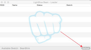
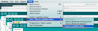
 Next, follow the instructions as mentioned in this portal for launch of Bean loader and Associate it to Arduino.Launch Arduino, and select these settings as shown.
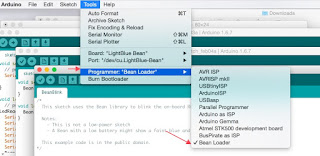
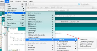
 Next, select the BeanBlink example and go to Arduino and click on Verify, followed by Upload.
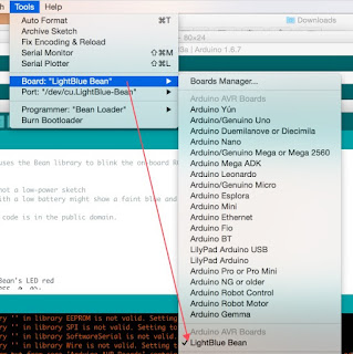
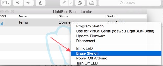
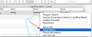
 Open the Bean Loader and right click on the connected, and Program sketch.
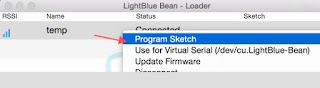 Once it successful in Uploading - the LEDs on the Bean should turn to Red, Blue and Green and continue until it is stopped by Right Click Connect-> Erase Sketch
 Troubleshooting tips:If the Bean does not connect from the Bean Loader, then remove the battery and retry inserting and connect the device from the Bean loader.If the Upload of sketch from Arduino does not happen then retry (I had to try it like 3 times before I got a successful Upload )Good luck on your tries and share your experiences with this device below.